

What Architectural Drawings for a Loft Extension Are
Architectural drawings for a loft extension are detailed plans that illustrate how an unused roof space can be converted into a functional living area. These drawings provide a clear visual and technical representation of the proposed layout, structural elements, and key design features within the existing property.
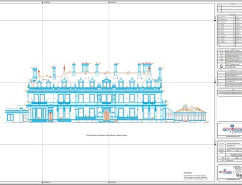
They typically include floor plans, elevations, and section drawings that show how the new space will integrate with the current building. By accurately documenting dimensions, structural components, and access points such as staircases or dormer windows, the drawings help ensure the project can be planned, approved, and constructed correctly.
Unlike rough concept sketches, professional architectural drawings are produced to a precise scale and follow established design and construction standards. This allows architects, engineers, and contractors to work from a shared set of accurate information throughout the project.
How the Drawings Are Produced
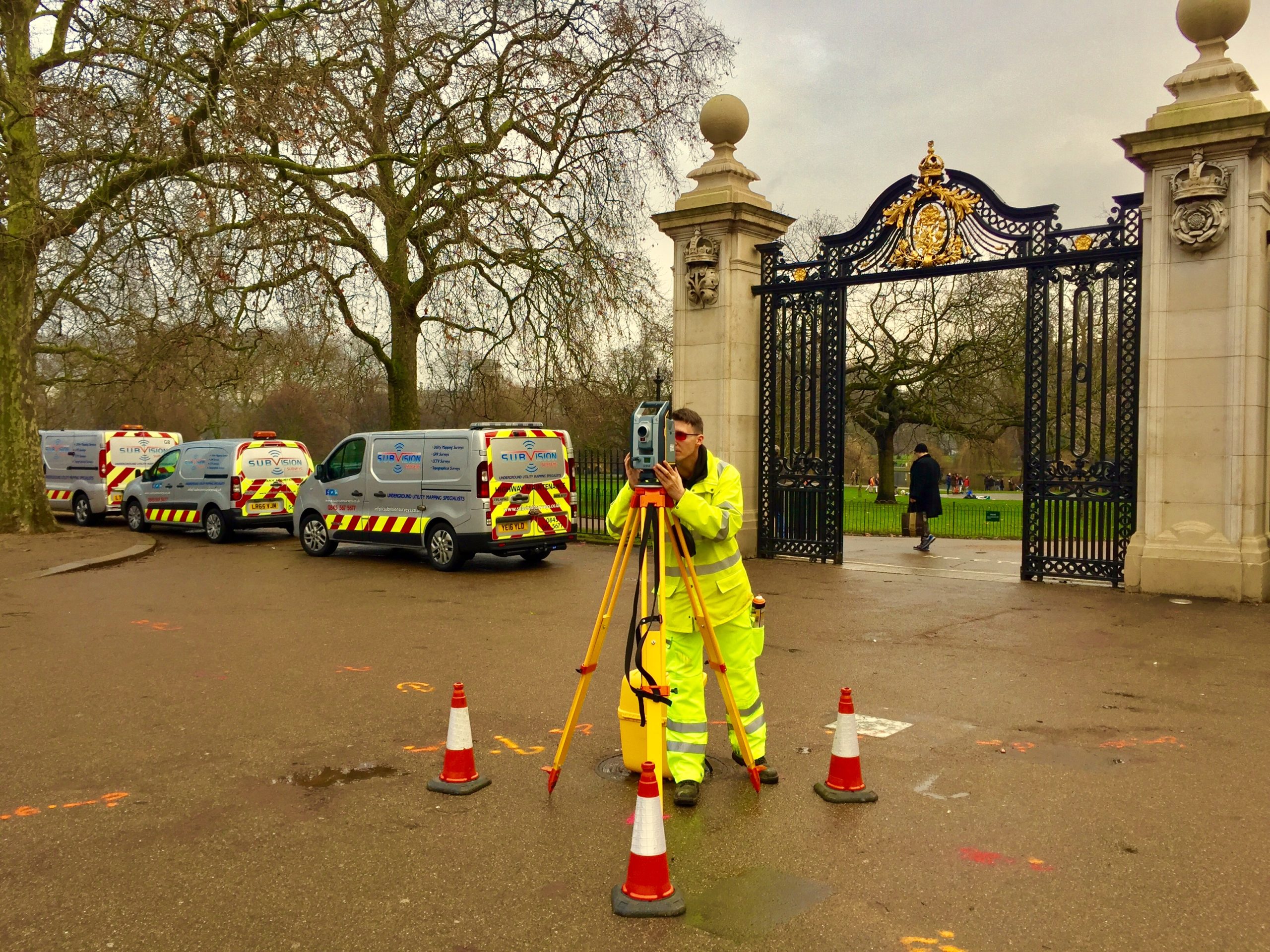
The process of creating loft extension drawings usually begins with a detailed survey of the existing property. Surveyors measure the structure, roof geometry, ceiling heights, and other key features to produce accurate base plans of the current building.
These measurements are then used to develop scaled drawings using specialised design software. The proposed extension layout is carefully planned to maximise usable space while maintaining compliance with structural requirements and local planning regulations.
During this stage, designers also consider practical elements such as natural light, head height, insulation requirements, and safe access via staircases. The resulting drawings provide a clear framework that supports both planning approval and construction.
How Architectural Drawings Improve Project Accuracy
Accurate drawings play a critical role in ensuring a loft extension is built correctly. Because the design is documented in detail before construction begins, potential issues can be identified and resolved early in the planning stage.
Precise measurements also help contractors understand the exact placement of walls, structural beams, windows, and stairs. This reduces the risk of costly mistakes or design changes during construction and helps maintain consistency between the proposed design and the finished build.
Clear architectural documentation also supports communication between everyone involved in the project. Builders, engineers, and local authorities can all reference the same information, ensuring decisions are based on accurate and reliable plans.
Practical Benefits for Homeowners and Builders
For homeowners, architectural drawings provide a clear understanding of how the finished loft space will look and function. They help visualise the layout, room proportions, and circulation within the extension before any building work begins.
For builders and contractors, detailed drawings act as a technical guide throughout the construction process. They provide the information needed to plan structural work, material requirements, and installation sequences efficiently.
Well-prepared drawings can also help streamline the approval process. Planning authorities and building control departments rely on accurate plans to assess whether the proposed extension meets relevant regulations and safety standards.
Using Architectural Drawings as Part of the Planning Process
While architectural drawings are essential for a loft extension, they form just one part of the overall planning and construction process. Structural calculations, planning permissions, and building regulations approval may also be required depending on the scope of the project.
Working with experienced surveyors and designers ensures the drawings accurately reflect both the existing property and the proposed changes. This helps create a reliable foundation for the project and supports a smoother transition from design to construction.






Leave A Comment